Bechelor of Technology
REC/NIT Hamirpur (H.P.),
India, [1998 - 2002].


WATER SUPPLY CALCULATION PROCESS
WATER SUPPLY CALCULATIONS
Proper design of water-distrubution system in a building is necessary to avoid excessive installed cost and in order that the various fixtures may function properly under normal conditions. The correct design results in piping, water heating, the storage facilities of sufficient capacity to meet the probable peak demand without wasteful excess in either piping or maintenance cost.
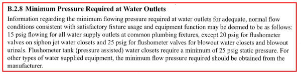
Minimum pressure required at water outlets
Minimum pressure required at fixture outlets shall be 15 psi according to the following standard code from the NSPC below.
We start our calculation using following four steps:
(1) Estimating Demand (Water Supply Fixture Units) - WSFU
(2) Calculating Pipe Sizes for the whole building (Cold and Hot Water System)
(3) Calculating Pipe Sizes for the whole building (Cold and Hot Water System)
(4) Calculating Friction Pressure Drops or losses in Cold and Hot Water Pipes
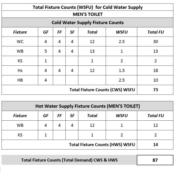
Step 1: Estimating Demand (Water Supply Fixture Unit) - WSFU
Using tables B.5.2 from NSPC code, we summaries the WSFU design data for each fixtures used.
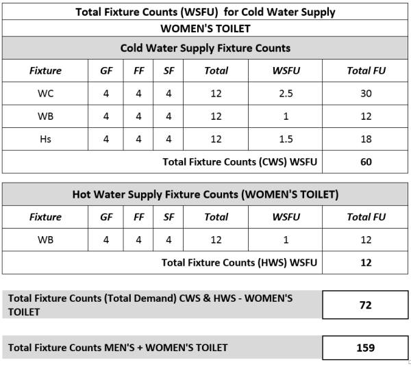
Consider a building design with the following fixture quantities. And using table B.5.2, we have following table:
Step 2: Converting demand in WSFU to GPM (Gallons per minute)
Using table B.5.4 for converting demand in WSFU to GPM.
We find that:
140 WSFU = 53 GPM (Flush Tank values)
160 WSFU = 57 GPM (Flush tank values)
Using Interpolation we find that,
159 WSFU = 56.8 GPM. Since 1 GPM = 3.785 L/m, therefore 56.8 GPM = 215 L/m
We find that we need 56.8 GPM (215 L/min) of water to feed this building.
Therefore, our booster pump flow rate shall be a minimum of 56.8 GPM (215 L/min)
Step 3: Calculating Pipe Size all building (Cold and Hot Water System)
LIMITATIONS OF VELOCITY: It is generally recommended that a maximum velocity at maximum probable demand in supply piping be limited to 8 fps (refer to attached NSPC, page 237 - "B.6 - Limitation of Velocity".
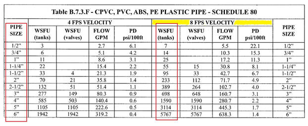
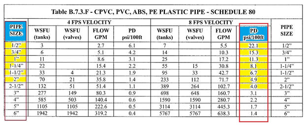
Using above table, we can size the CWS and HWS individual branch line for CPVC, PVC, ABS etc pipes. For all other pipes refer to general Table B.7.3.

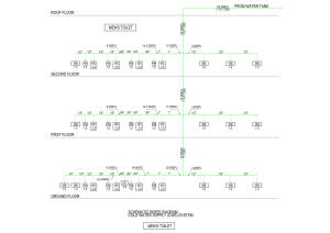
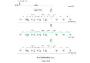
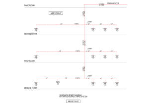
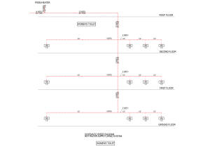
Refer to below scematic riser diagrams for sizing of water supply pipes using above tables.


Step 4: Calculating Major and Minor losses
(Calculating Friction Pressure Drops or losses in Cold and Hot Water Pipes)
We draw a schematic riser diagram for the longest path from the roof tank to the last fixture on the ground floor.
Using table B.7.3.F (for pipe losses - major loss & table B.9.7.D for fitting loss (minor losses).


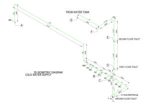

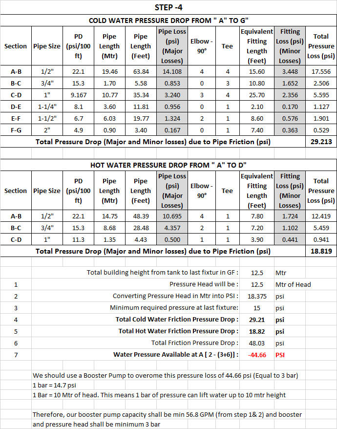
Take section A-B as a sample calculation:
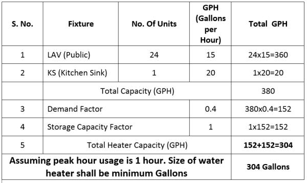
Calculating Water Heater Capacity:
This method utilizes average hourly data in gallons per hour (GPH) for various type of buildings. To calculate using this table 14.6, we count the fixtures, multiply the number of fixtures by the gallons per hour (GPH) for the fixture of that particular type of building and then add them. Then we multiply this total by the simultaneous usage factor to get the maximum hourly demand for the system. The minimum recommended storage volume then is calculated by multiplying the total demand by the storage factor.
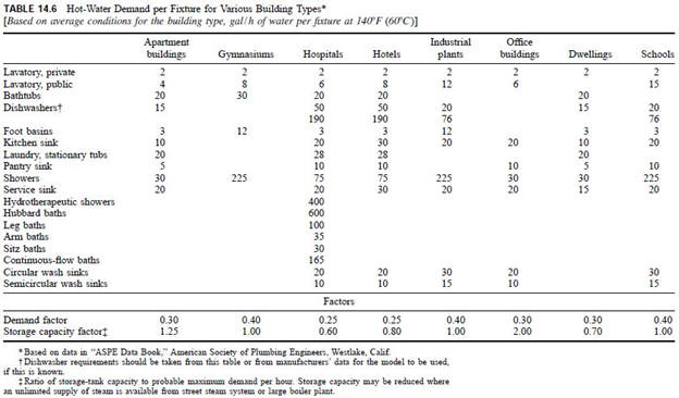
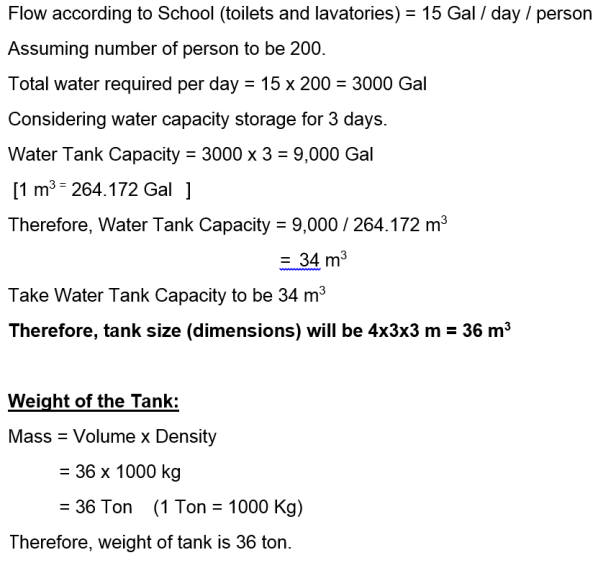
Consider this building is a school (for example). Using table 14.6 (Hot Water Demand per Fixture for various building type)
Water Tank Capacity Calculations