Bechelor of Technology
REC/NIT Hamirpur (H.P.),
India, [1998 - 2002].

AUTOMATIC FIRE SPRINKLER SYSTEM DESIGN
AUTOMATIC FIRE SPRINKLER DESIGN
1) Classification of Occupancies
Select the hazard type according to NFPA-13 (refer to attached).
Light Hazard Occupancies: where the quantity and / or combustibility of contents I slow and fires with relatively low rates of heat release are expected. Examples: Educational, Hospitals, Institutional, Museums, Residential, restaurant seating areas etc.
Ordinary Hazard (Group 1): where combustibility is low, quantity of combustibles is moderate, stockpiles of combustibles do not exceed 8 ft (2.4m), and fires with moderate rates of heat release are expected. Examples: Automobile parking and showrooms, bakeries, glass manufacturing, laundries, restaurant service areas etc.
Ordinary Hazard (Group 2): where combustibility and quantity of combustibles is moderate to high, stockpiles of content with moderate rates of heat release do not exceed 12 ft (3.66m) and stockpiles of contents with high rates of heat release do not exceed 8 ft (2.4 m) . Examples: Leather good manufacturing, Chemical plants, cereal mills, dry cleaners, Libraries -large stack rooms areas, machine shops, paper and pulp mills, repair garages, tire manufacturing, etc.
Extra Hazard (Group 1) : where the quantity and combustibility of contents are every high and dust, lint or other materials are present. Examples: Aircraft hangers, combustible hydraulic fluid, printing, rubber reclaiming etc
Extra Hazard (Group 2): where moderate to substantial amounts of flammable or combustible liquids are present. Examples: Flammable liquids spraying, open oil quenching, plastic manufacturing, varnish and paint dipping etc.
3) Pipe Material Specifications
Piping above ground for size upto 4 inches (100 mm) shall be Galvanized Iron, Seamless, Class’s’, Heavy duty - BS 1387 or according to Table 6.3.1.1. Pipe above 4” (100 mm) shall be Black Steel, Wrought Steel, Sch 40, Seamless or according to table 6.3.1.1
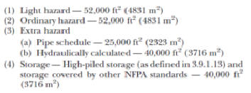
4) System Protection Area Limitations
The maximum floor area on any floor to be protected by sprinklers supplied by any one sprinkler system riser or combined system riser shall be as follows:
5) Protection Areas per Sprinkler
The protection area of coverage of the sprinkler shall be established by multiplying the S dimension by the L dimension, as follows: As = S x L
6) Maximum Distance from Walls
The distance from the sprinklers to wall shall not exceed on-half of the allowable maximum distance between sprinklers. The distance from the wall to the sprinkler shall be measured perpendicular to the wall.
7) Minimum Distance from Walls
Sprinklers shall be located a minimum of 4 inch (102 mm) from the wall.
8) Minimum Distances between Sprinklers
Sprinklers shall be placed not less than 6 ft (1.8 m) on centre.
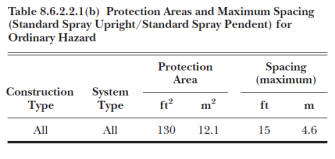
9) Protection Area of Coverage and Maximum Spacing between Sprinklers
The maximum allowable protection area of coverage for sprinklers (As) shall be in accordance with value indicated in Table 8.6.2.2.1(a) for Light Hazard occupancies, Table 8.6.2.2.1(b) for Ordinary Hazard occupancies, Table 8.6.2.2.1(c) for Extra Hazard occupancies, Table 8.6.2.2.1(d) for High- Piled Storage.
10) In-rack sprinklers shall be permitted to be placed less than 6 ft (1.8 m) on centre.
11) Distance below Ceilings
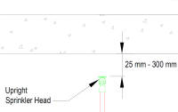
Under unobstructed construction, the distance between the sprinkler deflector and ceiling shall be minimum of 1 inch (25.4 mm) and maximum of 12 inch (305 mm) throughout the area of coverage of the sprinkler.
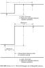
Under obstructed construction, the sprinkler deflector shall be located in accordance to below figure 8.6.4.1.1.3.
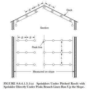
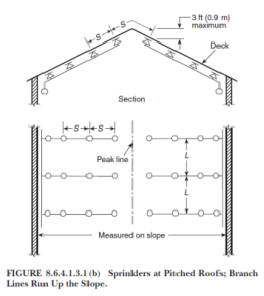
12) Sprinkler under Peak of roofs and Ceiling
Sprinkler under peak of roofs and ceiling shall be in accordance with below Figure 8.6.4.1.3 (a) and Figure 8.6.4.1.3 (b).

13) Protection Area of Coverage and Maximum Spacing for Side Wall Sprinklers
The maximum allowable protection area of coverage for sprinklers and maximum distance between them shall be in accordance with value indicated in Table 8.7.2.2.1.
14) Extended Coverage Upright and Pendent Spray Sprinklers - Protection Areas and Maximum Spacing. Table 8.8.2.1.2.
15) Protection Areas and Maximum Spacing for CMSA (Control Mode Specific Application) Sprinklers. Table 8.11.2.2.1
16) Protection Areas and Maximum Spacing for ESFR (Early Suppression Fast-Response) Sprinklers. Table 8.12.2.2.1
14) Rated Pressure
System components shall be rated for the maximum system working pressure to which they are exposed but shall not be rated at less than 175 psi (12.1 bar) for components installed above ground and 150 psi (10.4 bar) for components installed underground.
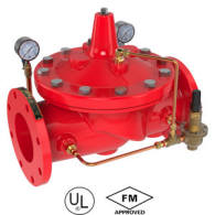
15) Pressure Reducing Valves
If water pressure in excess of 175 psi (12.1 bar), a listed pressure reducing valve shall be installed and set for an outlet pressure not exceeding 165 psi (11.2 bar) at the maximum inlet pressure.
Pressure gauges shall be led on the inlet and outlet sides of each pressure reducing valves.
A relief valve of not less than 13 mm in size shall be provided on the discharge side of the PRV to set to operate at a pressure not exceeding 175 psi (12.1 bar).
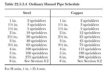
16) Pipe Sizes
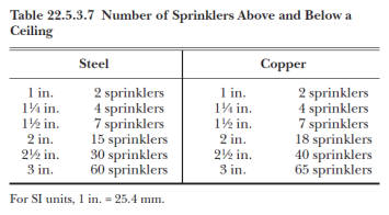
Pipe sizes shall be in accordance with Table 22.5.2.2.1 for Light Hazard Pipe Schedules, Table 22,5,3,4 for Ordinary Hazard Pipe Schedule, Table 22.5.3.7 for Upright Sprinklers Above and Pendent Sprinklers below a Ceiling and pipe sizes for extra hazard shall be hydraulically calculated (Table A.22.5.4 for reference purpose only).
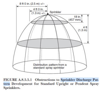
17) Sprinkler Discharge Patter (Figure A.8.5.5.1)
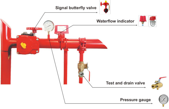
18) Floor Control Valve Stations (also called Zone Control Valve Assembly)
Zone Control Valve is a system designed to separate the area in case of maintenance and to get the indication of fire zone on a combination of Butterfly valve, Flow Switch, Pressure Gauge and Test & Drain Valves.
Its main purpose it to regulate water flow in the designated “zones” or areas and in some buildings, by floors / levels, thus named zone control valve.
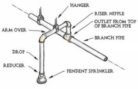
19) Pipe Supports and Hangers
20) Branch Pipe shall not exceed 8 Sprinklers.
On a branch pipe we can only install maximum up to 08 Nos. of sprinklers
21) Sprinkler Head installation without false ceiling:
Distance between slab and sprinkler shall be minimum 1" (25 mm) and maximum 12" (300 mm)
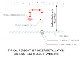
22) Pendent sprinkler heads installation when false ceiling height is less than 80 cm.
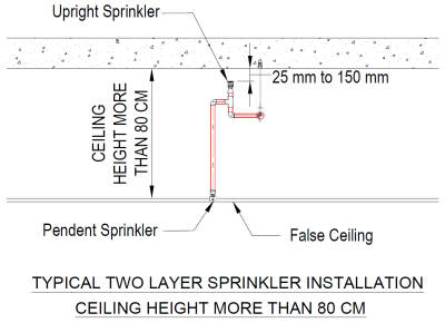
23) Two layer sprinkler heads when false ceiling height is more than 80 cm.
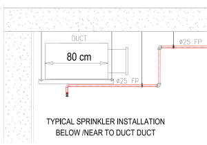
24) Install one sprinkler below any duct or cable tray when width is more than 80 cm below.
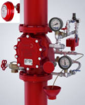
25) Installation Control Valve (Also called Alarm Check Valve)
26) Local alarms shall be provided on all sprinklers system having more than 20 sprinklers.
An alarm check valve is basically a check valve with an alarm port. The main purpose of the alarm check valve is to ring a mechanical bell called a water motor gong. The valve should, (if properly maintained), help hold the system pressure steady and reduce the possibility of false alarms.
The alarm check valve is a water flow alarm device designed for vertical installation in the main supply to a wet pipe sprinkler system. When a flow of water from the system equals or exceeds that of a single sprinkler, the valve is to actuate a fire alarm.
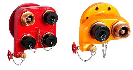
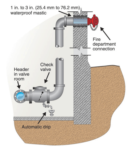
27) Fire Department Connection
A fire department connection shall be provided as described in accordance with Figure 8.17.2.1. Pipe size shall be a minimum 4 in (100 mm) for fire engine connections and 6 in 9150 mm ) for fire boat connections.
The FDC shall be on the system side of the water supply check valve.
The FDC shall be on the street side of the building. A listed check valve shall be installed in each fire department connection.
There shall be no shut-off valve in the FDC piping.
28) Sprinklers shall be installed beneath all stairways of combustible construction.
29) One sprinkler shall be installed at the top of the vertical shaft.
30) Sidewall sprinklers shall be installed at the bottom of each elevator hoisting not more than 2 ft (0.61 m) above the floor of the pit.
31) Upright and pendent sprinklers shall be installed at the top of the elevator hoist ways.
32) Open grid ceiling shall not be installed beneath sprinklers.
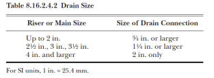
33) System Main Drain
34) Auxiliary drains shall be provided where there is change in piping direction prevents drainage of system piping through the main drain valve.
35) Provision for flushing:
All sprinkler systems shall be arranged for flushing. Readily removable fittings shall be provided at the end of all cross mains. All cross main shall terminate in 31.8 mm or larger. All branch lines or gridded system shall be arranged to facilitate flushing.
36) Automatic Sprinklers shall be installed in:
A) Basement used as a car parks or storage occupancy if the area exceed 200 m2.
B) Multilevel basements.
C) Any room or other compartment of a building exceeding 1125 m2 in area.
D) Departmental stores or shops, if the aggregate covered area exceed 500 m2.
E) All non-domestic floors of mixed occupancy which constitute a hazard and are not provided with staircase independent of the remainder of the buildings.
F) Godowns and warehouses as considered necessary.
International Experience:
A) 55% of fires were extinguished by the operation of two or less sprinkler heads.
B) 80% of fires were extinguished by the operation of eight or less sprinklers.
C) 90% of fires were extinguished by the operation of 18 or less sprinkler heads.
D) Sprinkler coverage for the fire protection of occupancies has full legislative as well as insurance supports.